Fixtures / Axle housing fixtures
Axle housing machining fixtures
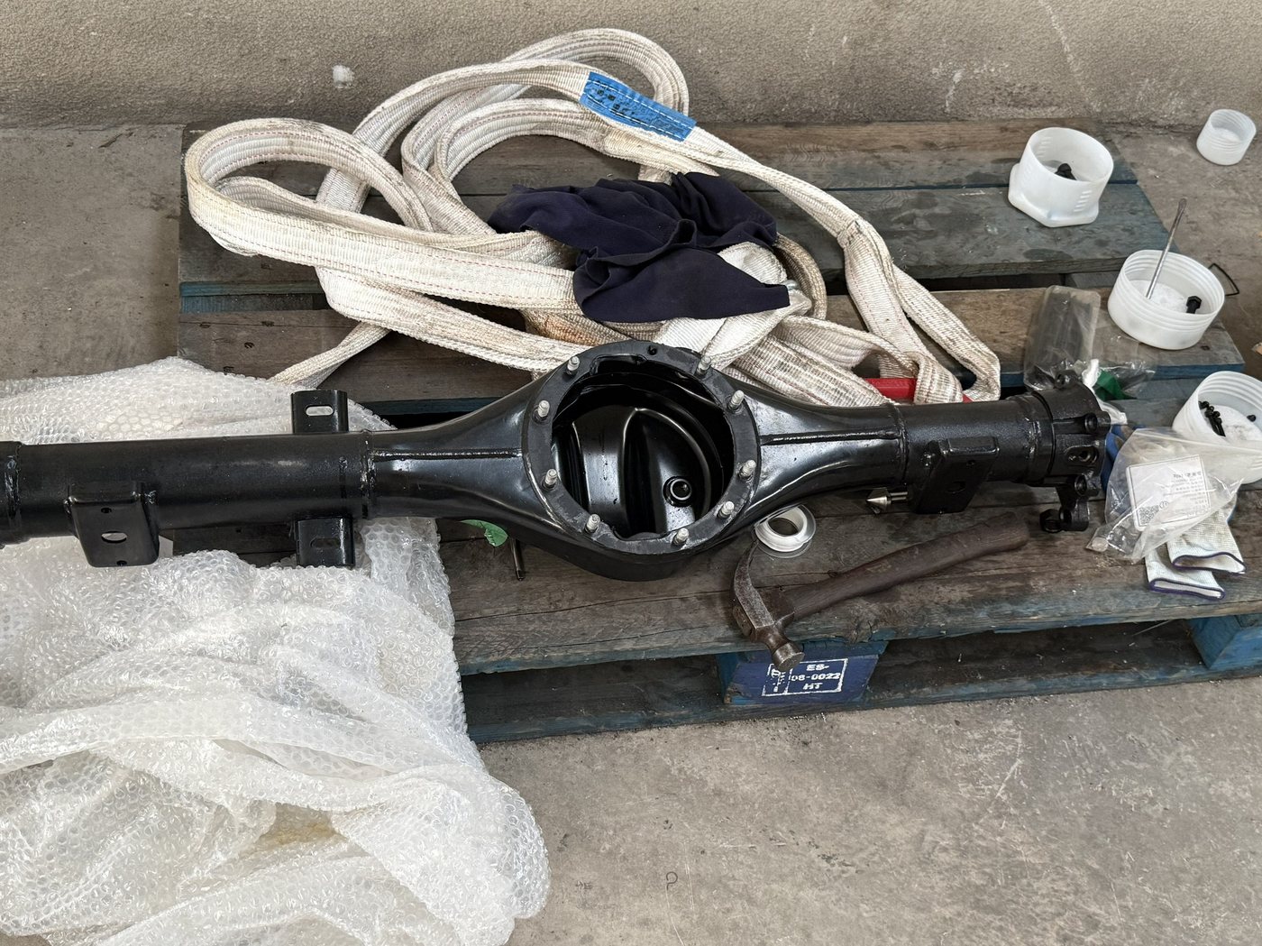
An axle housing is a long, thin-wall casting with two co-axial bearing bores at opposite ends and a bowl in the middle. Clamp it in the obvious way and it springs: the bores measure round off the machine and oval on it. The fixture is the part of the process that decides whether that happens.
At a glance
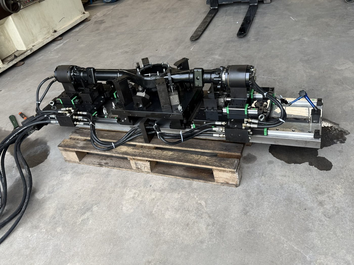
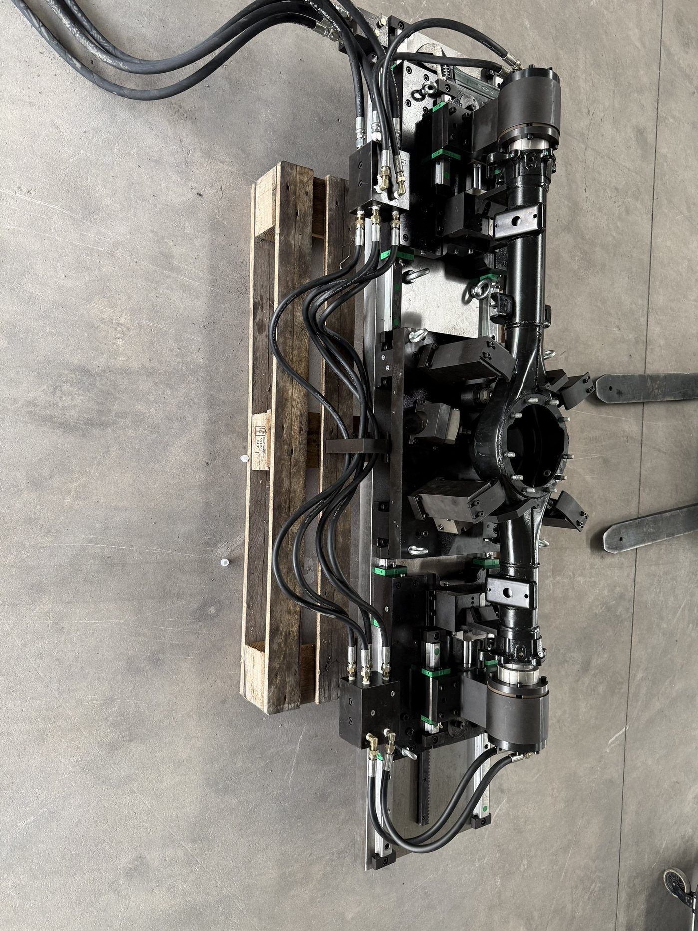
What it is: a dedicated fixture that locates an axle housing on three points plus two bores, supports the bowl and the tube underneath with floating supports, and clamps from above in a defined order — so that clamping force closes the part against the supports instead of bending it.
Typical configuration: hydraulic multi-station, one or two parts per cycle, mounted on a sub-plate for an HMC pallet or a VMC table. Clamp confirmation on every station.
Price band: USD 16,000–45,000 FOB China for a hydraulic multi-station set, depending on station count, whether the power unit is included, and how much of the datum scheme has to be designed from scratch.
Lead time: 8–12 weeks from approved drawing to trial cut; add 4–6 weeks for sea freight.
The single number that decides whether this fixture works: the position tolerance between the two bearing bores. On a fixture that clamps the tube directly, that number moves with clamping force. On one that clamps down onto supports, it does not.
What can be specified
| Item | Range |
|---|---|
| Workpiece | Drive axle housing, typically 900–1,600 mm overall length |
| Material | Cast steel or nodular iron; thin-wall sections down to 6–8 mm |
| Location | Three primary pads plus two bores (one round, one diamond), or a face-and-two-pin scheme |
| Supports | Spring or hydraulic floating supports under the bowl and both tube ends, locked before clamping |
| Clamping | Hydraulic swing or link clamps, sequenced: supports contact → lock → clamp |
| Stations | 1 or 2 per fixture; two fixtures per pallet on an HMC |
| Position tolerance | Typically 0.05 mm true position between bearing bores; tighter requires in-process checking |
| Clamp confirmation | Pressure switch per circuit plus position sensing on each clamp (typical) |
| Interface | Sub-plate on an HMC pallet, or T-slot base for a VMC table |
| Delivery package | Drawings, BOM, hydraulic circuit, M-code list, trial-cut report, packing spec |
Figures marked “typical” are the values this class of fixture normally holds in production. Actual values are fixed on the drawing, not on this page.
Why axle housings distort, and where
Three things happen when a housing is clamped badly, and they happen in this order.
The tube bows. Clamping the tube from the side pushes the two ends apart or together, and the bearing bores lose co-axiality. The bores are then machined true to the machine and untrue to each other.
The bowl face lifts. The bowl is the stiffest part of the casting and the tube is the most flexible; a clamp over the bowl loads the tube, not the bowl. The face is machined flat and springs when released.
The part relaxes after the cut. Thin-wall castings carry residual stress from casting and from roughing. Material removed from one side redistributes it, and the finished bore moves after the fixture is opened — sometimes by more than the tolerance.
None of this is a machining problem. All three are decided by where the part is supported and in what order it is clamped.
The sequence matters more than the clamp force
The order this fixture runs is fixed, and it is fixed for a reason:
- Seat on the three primary pads. The part goes down under its own weight, located on the machined datum, not on the raw casting.
- Bring the floating supports into contact and lock them. The supports touch, then lock — they do not push. A support that pushes lifts the part off its primary datum.
- Clamp down onto the supports. Force goes from above, through the part, into a locked support underneath. Nothing bends.
- Confirm, then cut. Every clamp confirms before the program advances.
Most of the distortion complaints we see come from a fixture that does steps 3 and 4 but skips step 2, or runs 2 and 3 from the same hydraulic circuit so the support and the clamp fight each other.
A sequence valve that holds the clamp circuit closed until the support circuit reaches its set pressure solves it mechanically. On a Mazatrol control the same thing can be done in the ladder with two confirmation inputs, but only if the fixture has two separate circuits to confirm.
What this fixture is not for
Being clear about the boundary saves both sides a month.
- Not a first-operation fixture. It locates on machined datums. The first operation, on raw casting, needs a different scheme entirely.
- Not for reworking distorted parts. If the casting is already out of tolerance before machining, a fixture holds the error, it does not correct it.
- Not a substitute for stress relief. If the casting is not stress-relieved, the part will move after machining no matter how good the fixture is. That is a foundry conversation, not a fixture conversation.
Send a drawing. Get a clamping scheme and a price band.
What speeds this up: the workpiece drawing (STEP plus a PDF with datums and tolerances), the machine model, the operation sequence, the cycle time you are targeting, and the annual quantity. Without those you get a band; with them you get a number.